The installation template is extended according to temperature and humidity.
Fan coil unit installation guide.
For slopefan coils use kit part no.
Do not drill any holes in the casing of the unit to install the option.
496 01 5503 02 horizontal right conversion of units with a coils 1.
Check on dimensions in use.
Only use the accessories provided by daikin to install the option.
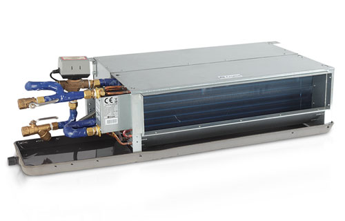
Unit installation about fan coil installation please refer to the dimensional drawings and installation diagram.
Connection of first valve.
Installation guide operating manual.
The functions mentioned in the installation manual of the ekrp1c11 can not be used.
Preface krueger fan coils represent a prudent investment which can with proper installation operation and regular maintenance give trouble free operation and long service.
1 communication to fan coil pcb 2 power supply wire to fan coil unit 3 fuses 5 a 250 v 4 yc y1.
This allows for modular unitstobedisassembledandcomponentsmovedseparately to installation area for reassembly.
Hl series c horizontal low profile fan coil unit.
The dimensions of the installation template are the same as those of the.
Fem4x fem4p rem4x fxm4x 6 specifications are subject to change without notice.
P series t701dfp installation guide operating manual.
The ekrp1c11 can only be used to connect the valves.
Installation instructions supplied with kit for proper installation.
Fix the standard unit to the ceiling or wall using at least 4 of the 6 slots.
Unit installation measure and mark the position for the hanging rod.
Drill the hole for the angle nut on the ceiling and fix the hanging rod.
Gasket kit number kfahd0101slp is also required for.
Fora coils use kit part no.
Allow space for wiring piping and servicing unit.
Your equipment is initially protected under the.
Use fireproof resilient gasket 1 8 to 1 4 in 3 to 6 mm thick between duct unit and floor.
Fem4x6000b rem4x6000b and fxm4x4800 6000 fan coils are two piece modular units.
Procedure 2 mount fan coil unit can stand or lie on floor or hang from ceiling or wall.
N series f series and v series tec3000 color screen product bulletin catalog sales flyer.
Install or service any unit without following safe practices regarding mechanical equipment.
Note to ensure proper drainage for horizontal installations unit must be installed so it is within 1 8 in.
Figure 2 upflow installation.
N for horizontal installation ceiling mounting it is advisable to use m8 thre aded bars screw anchors suitable for the unit s weight and to arrange for the positioning of the unit using 2 m8 bolts and a washer the diameter of which is suitable for inserting the slot and for then fixing the unit.
Level of the length and width of unit.
Remove blower and coil access panel and fitting panel refer to figure 6.
Installation instructions fan coils.
Remove coil mounting screw securing coil assembly to right side casing flange.

